KBIC65 build log
Overview of build steps
- Prepare nice!nano
- Set up ZMK and generate uf2 file
- Load firmware with keymap
- Prepare foam/rubber layers (optional)
- Attach plate foam
- Cut out neoprene sheet
- Prepare bottom plate
- Attach rubber feet
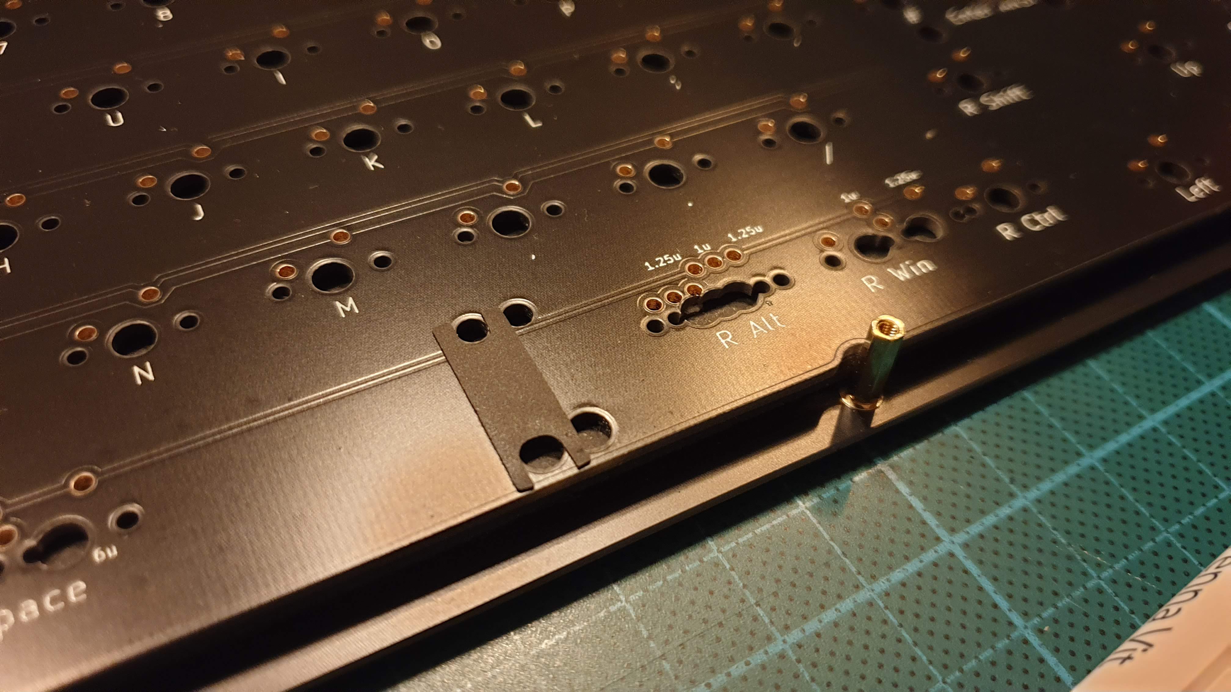
- Attach spacers to align components
- Prepare PCB
- Solder on diodes
- Socket nice!nano
- Test PCB
- Prepare and attach stabilizers
- Stabilizer foam / band-aid mod
- Clipping (not necessary)
- shrink tube mod (reverted after testing)
- Lube
- Attach stabilizers
- Assemble plate-PCB package
- Attach and solder on switches
- Test assembled module
- Assemble keyboard without battery
- Test keyboard
- Add battery
- Test again (now with Bluetooth!)
- Put on keycaps
- Enjoy!
- Remember you were supposed to put on am acrylic window, order it and wait
Recommended components
- 1 KBIC65 PCB
- 1 KBIC65 bottom plate
- 1 KBIC65 switch plate
- 1 KBIC65 2 mm acrylic window
- 1 nice!nano
- 70 1N4148 diodes
- 6 domed rubber feet
- 24 M2 x 4 mm brass bolts
- 8 M2 x 10 mm female-female brass standoffs
- 4 M2 x 15 mm female-female brass standoffs
- 4 M2 x 3 mm male-female brass standoffs
- 70 MX-style switches
Bolts and standoffs are most easily acquired via AliExpress, at least in Sweden where I am.
And if you want to put in foam
- 3-5 mm bottom-PCB foam or rubber (there is 3 mm clearance, 5 mm requires cutting out holes around pins sticking down). I used 3 mm neoprene plus some leftover plate foam on the sides to seal it.
- Plate-PCB foam
Prepare nice!nano
I had been looking at how to create a custom wireless keyboard for a while. My initial research suggested using an Adafruit Feather BLE with QMK, such as the Dissatisfaction65 by Nicell, but luckily just a few months earlier Nicell himself had created the nice!nano controller, which is a ProMicro footprint Arduino close with Bluetooth. Even better, I found there was a relatively new keyboard firmware project called ZMK, that addressed a bunch of the issues that QMK has with wireless. The two primary issues resolved by ZMK is (1) more battery-efficient scanning algorithms to improve battery life and (2) a license that is compatible with the Bluetooth libraries since QMK is not legally compatible with the libraries required to run Bluetooth chips.
In addition, however, ZMK has learned a lot from how QMK is used and also improved other aspects of the project, such as minimal user repositories that hosts your personal keymap and keyboard configurations and that then builds the ZMK firmware using GitHub Actions. A really neat setup in my opinion. Of course, they still don’t have VIA or something like the QMK web tool, but in my case I was building my own PCB and matrix and therefore would need to dig into some code either way.
ZMK has pretty good documentation, but it also helped looking at other ZMK user repositories. My recommended reading guide order someone new to ZMK and that would like to replicate my work would be
- Read the introduction
- Read the FAQ and understand the difference between board and shield
- Set up a ZMK user repo
- Create a new shield
I then used the Nibble ZMK shield as a reference, there are probably better options though since the Nibble has an extra column to the left, a multiplexer for the matrix and support for rotary encoders, all of which I didn’t need for my build.
I then created a first keymap, pushed to my personal config repo and with some ZMK GitHub Actions magic I could download a uf2 file to flash my nice!nano with.
The nice!nano was super-easy to flash with a new firmware since it uses a bootloader that makes it show up as a mass-storage device. Then it is simple copy-paste or drag-and-drop of the new .uf2 file to the device and once the transfer is complete it automatically flashes itself and voilà, a new keyboard is detected.
Prepare foam and rubber
Plate foam
This is my second keyboard build, my first was a KBD75v2 kit from KBDfans. For that build I got plate foam and I had enough leftover to also cover this build. The modular plate foam is most easily placed using a tweezer to avoid deforming the pieces to much before the glue touches the plate. I also tried to keep the surrounding edges clean since they will be visible from the sides.
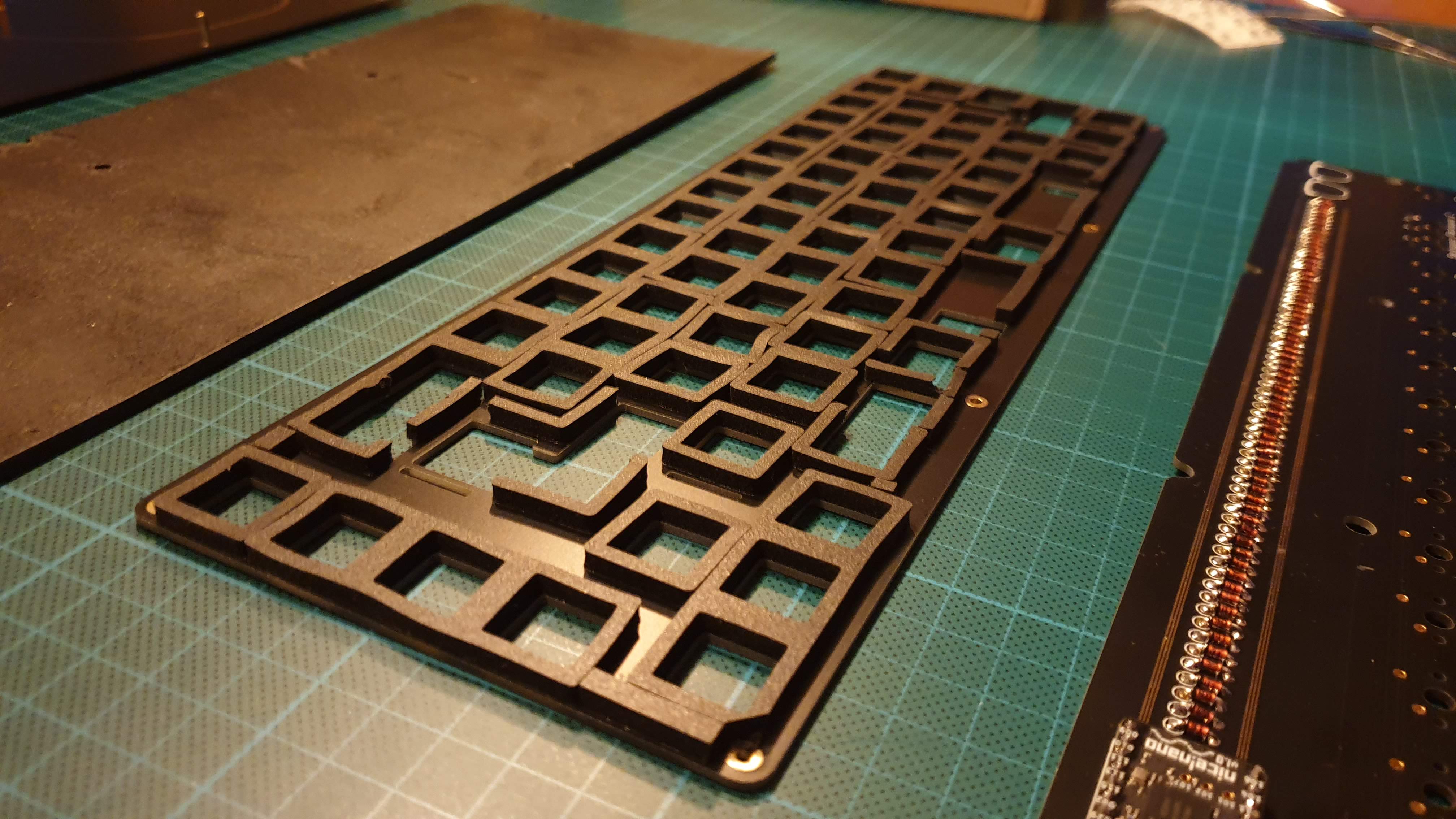
Unfortunately, I was a little too eager with covering everything. It turned out when I was assembling the plate and PCB that some of the foam I had put in around the stabilizers was pressing on them, so I had to disassemble my work so far and clean up all the foam above and below the stabilizer mounts and along the stabilizer wire.
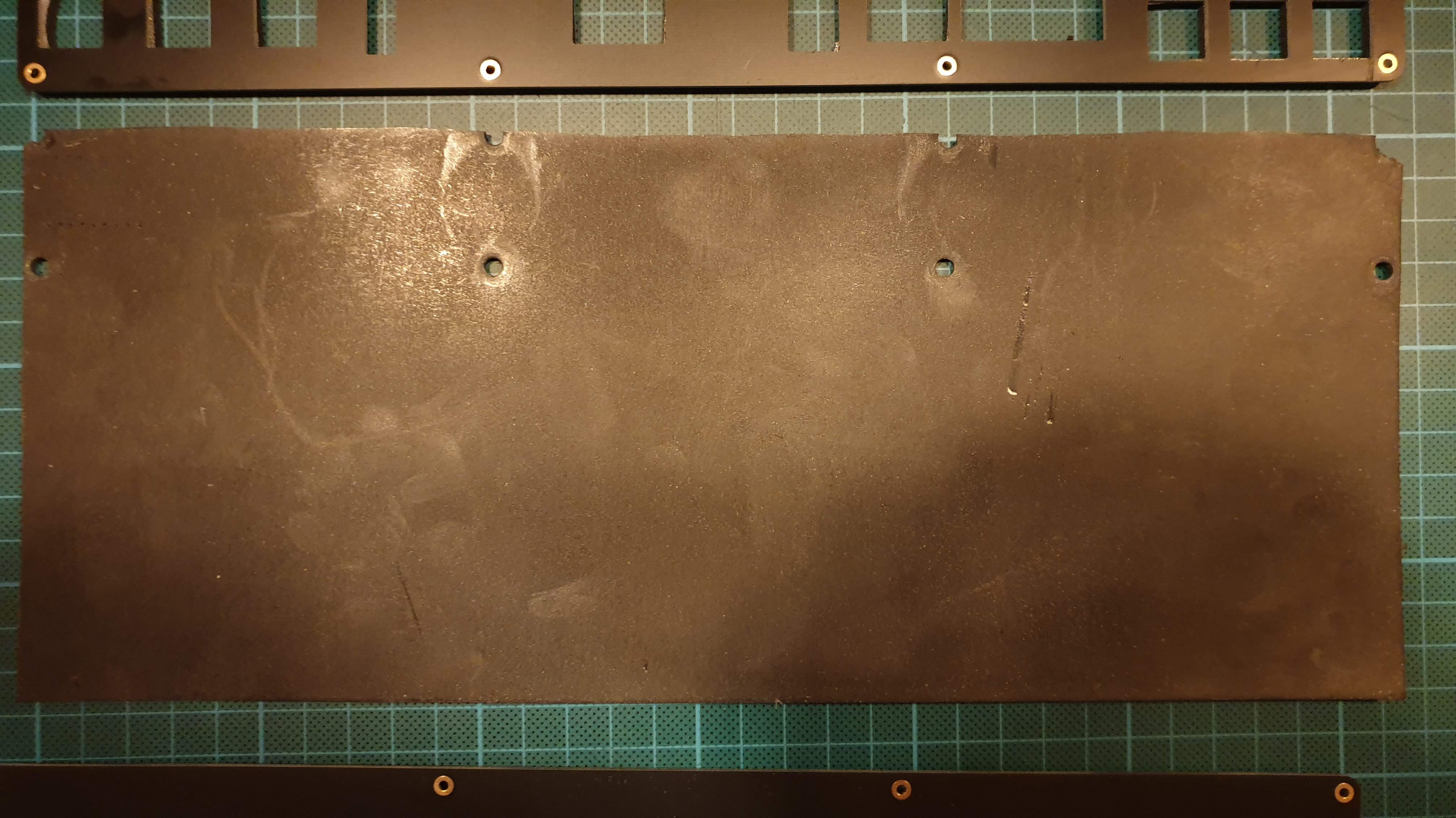
Case foam/rubber
To add some weight and sound dampening without impeding the wireless signal too much, I decided to add a 3 mm thick neoprene rubber cutout between the PCB and the bottom plate. I took one of my spare PCBs and used it to draw the outline on my neoprene sheet and then I used a carpet knife and a hole puncher to create the shape.
Some notes on silencing a mechanical keyboard (or controlling sound profile)
Doing some research on how to dampen the sound of the keyboard (since I want to use it at my office in the future without pissing off my colleagues) the factors that I have understood to be most important, and think makes sense from my limited experience with two keyboards are the following
- Use a silent linear, silent tactile, linear or tactile switch (on order of most to least silent), a clicky switch is by definition not silent.
- Weight is one of the most important factors, the heavier the better so metal cases are better than plastic ones. This goes in conflict with a wireless build so I opted to aim to make the keyboard as heavy as possible without using metals that might shield the Bluetooth signal.
- Put the keyboard on a soft desk mat.
- Fill up hollow spaces in the keyboard with foam, rubber or some other material. Foam makes most sense usually since it probably has the least impact on the flexibility and motion of the plate and thus the give with each keystroke.
- Use a softer plate material, aluminum is usually considered OK among metal but brass and steel might cause ping sounds.
- Band-aid mod stabilizers and possibly shrink tube mod them.
- Lube stabilizers
- Lube switches
If you have done all of the above and want to try something else, you can try - Putting O-rings on the key cap stems. The idea with this is that it will dampen the sound when bottoming out, but it might also make the keys feel more mushy and reduces key travel somewhat. If and how well it works also depends on your key cap profile and materials. This mod is a very loaded subject on r/mk and I think it has very little impact compared to the points above.
- Fill larger keycaps, or if you’re extreme all keycaps, with foam to remove and reverb inside the keycap. This mod is most commonly done for the space bar.
Choice of case foam
Since I wanted my case foam to both be a good sound absorber and provide as much weight as possible the options I found most suitable were:
- Sorbothane: Expensive and hard to get in a good size if you have an open case design as my first iteration will be
- Butyl rubber or similar: Used for sound deadening in cars and the best alternative I found was something like Dynamat Dynaliner. Issues with this was once again price but I also read that it can smell quite a bit and it takes a while before the smell goes away, which again is maybe not the best choice with an open case design. The benefit would, however, be that it is probably the heaviest of the options around.
- High-density EVA foam: Relatively cheap but dense foam commonly used for cosplay and role playing.
- Neoprene rubber: Also relatively cheap and available.
Comparing these I ruled out sorbothane and butyl rubber, leaving HD-EVA and neoprene. Out of these I then looked up the common densities of these materials and neoprene won by a small margin so I settled on neoprene.
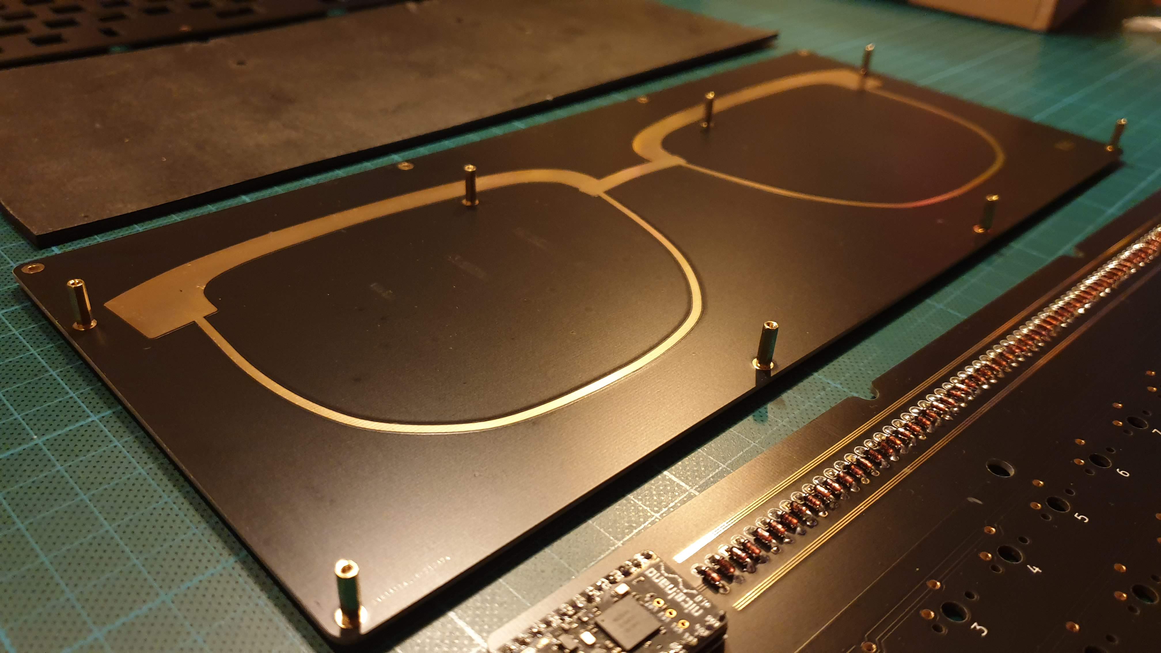
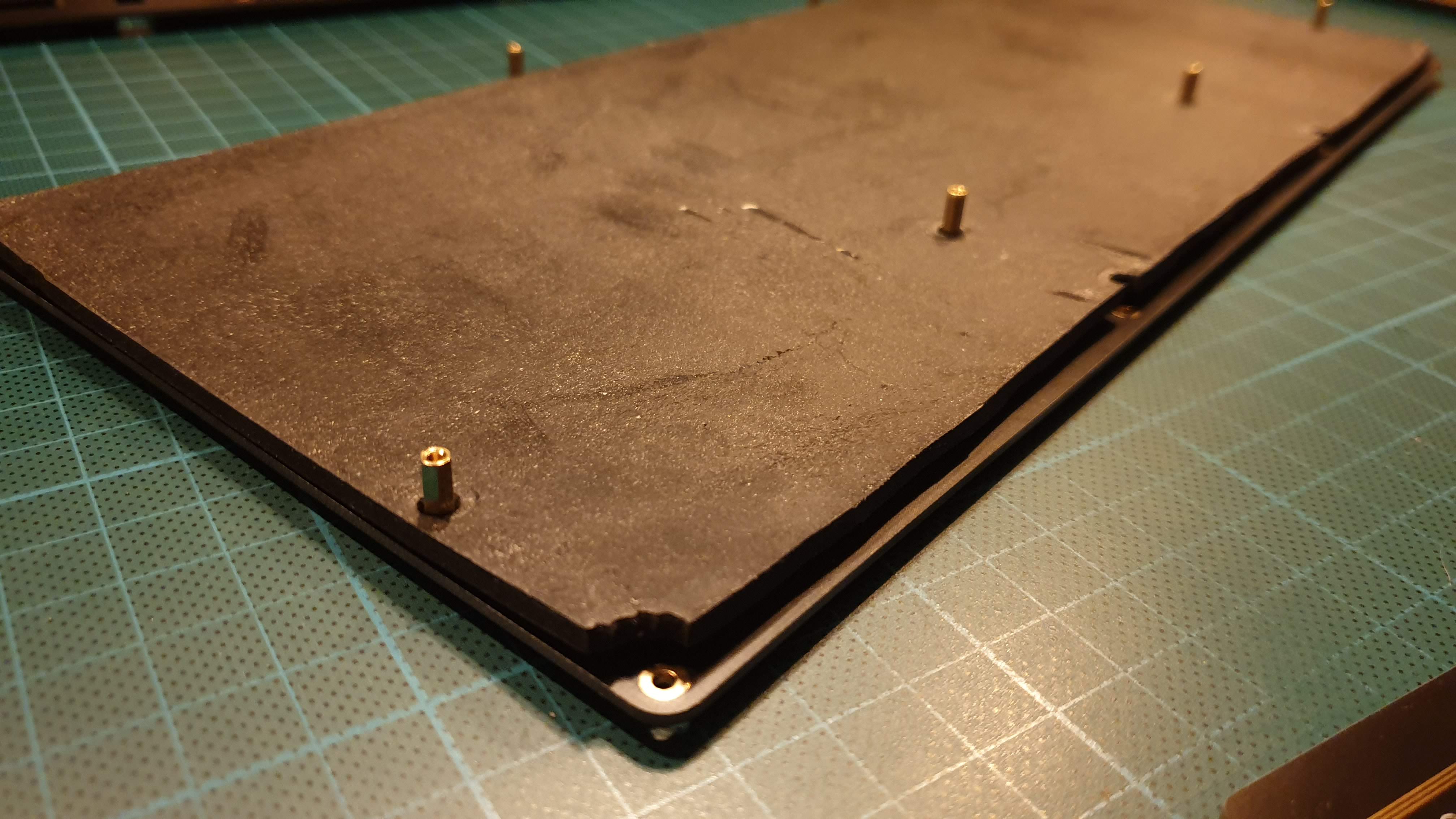
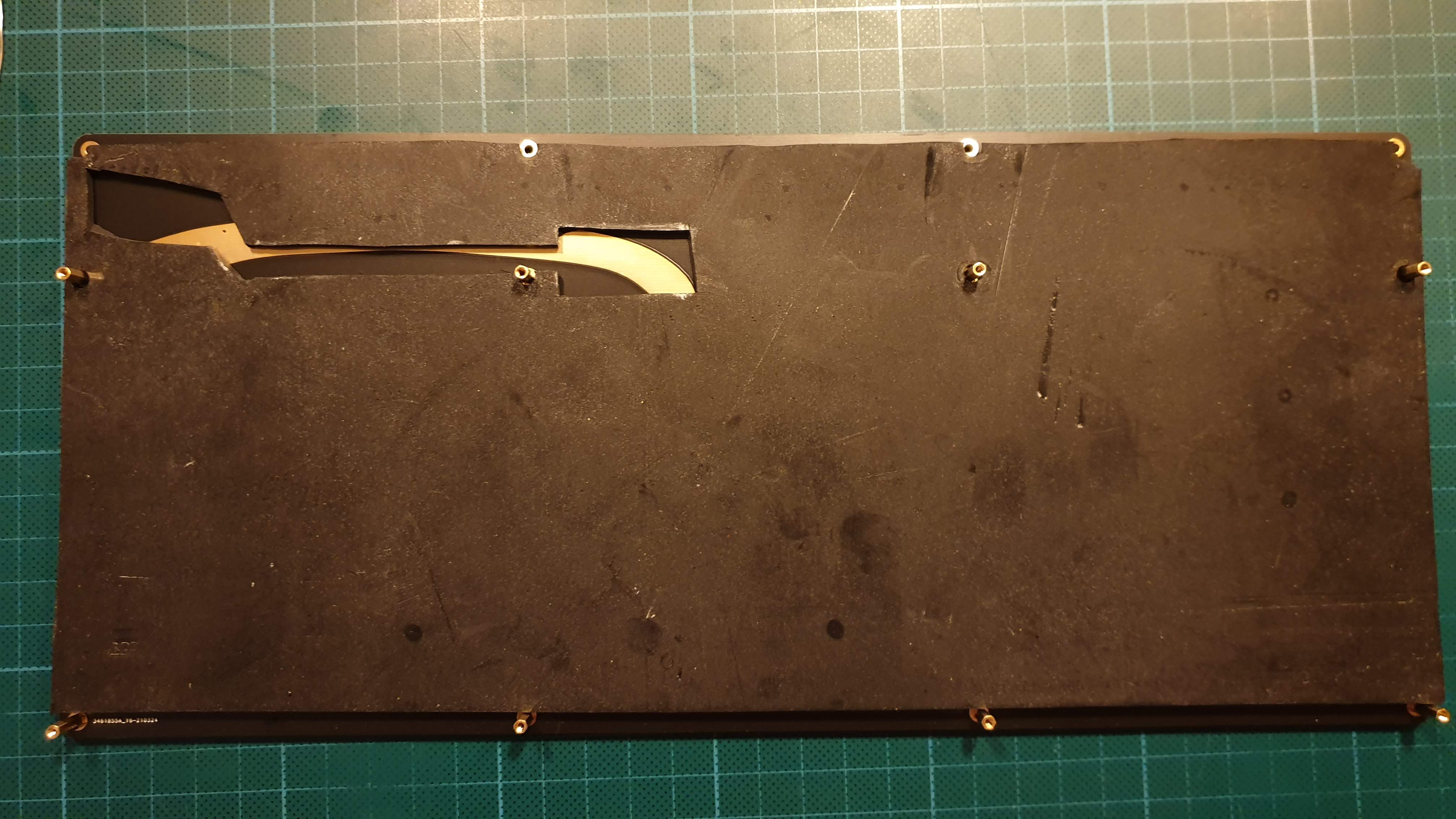
Prepare bottom plate
As they always say in keyboard build videos, start with putting rubber feet on your case to protect it from scratches. In addition, it will also be nice to occasionally use the bottom and neoprene sheet as a base when working with the PCB and plate.
For screws and spacers I wanted them to be in brass, or look like golden brass at least. This was a bit tricky to find in Sweden, but I eventually learned that Amazon is a pretty good source for random screws and I picked up this kit, giving me some flexibility if I want to play with the mounting. I attached 10 mm spacers to the bottom and then put the neoprene on for the moment. The neoprene feels like a good soft surface to rest the PCB once diodes, controller and switches are soldered in.
Prepare PCB
There is no real test like getting something to run in real life. I ran checks in KiCad when developing my PCB and in addition, JLCPCB do probe testing to check the PCB. I could, of course, have messed up something more fundamental in my design that wouldn’t be caught in any of these checks.
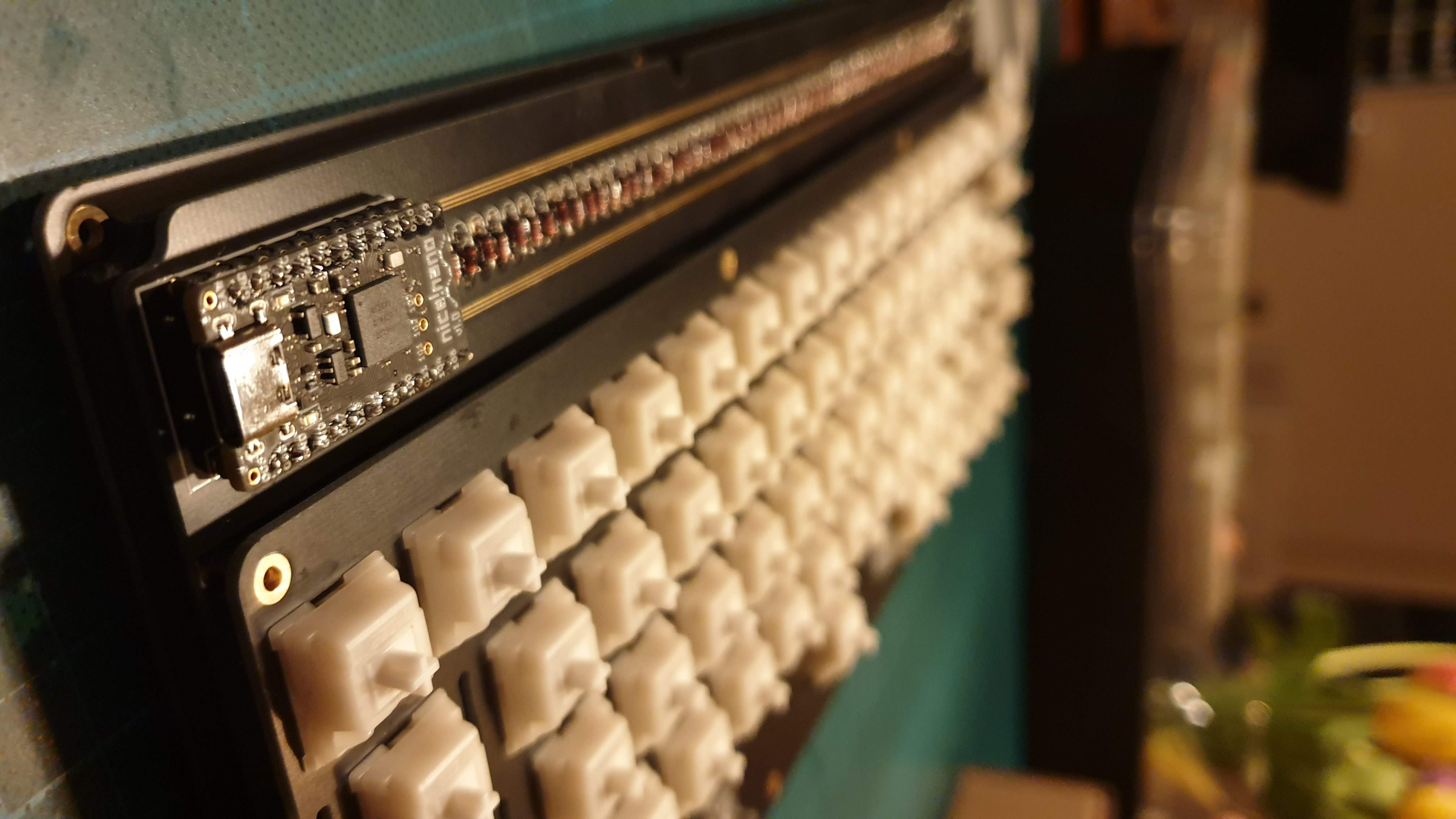
To get the PCB up and running required two general steps
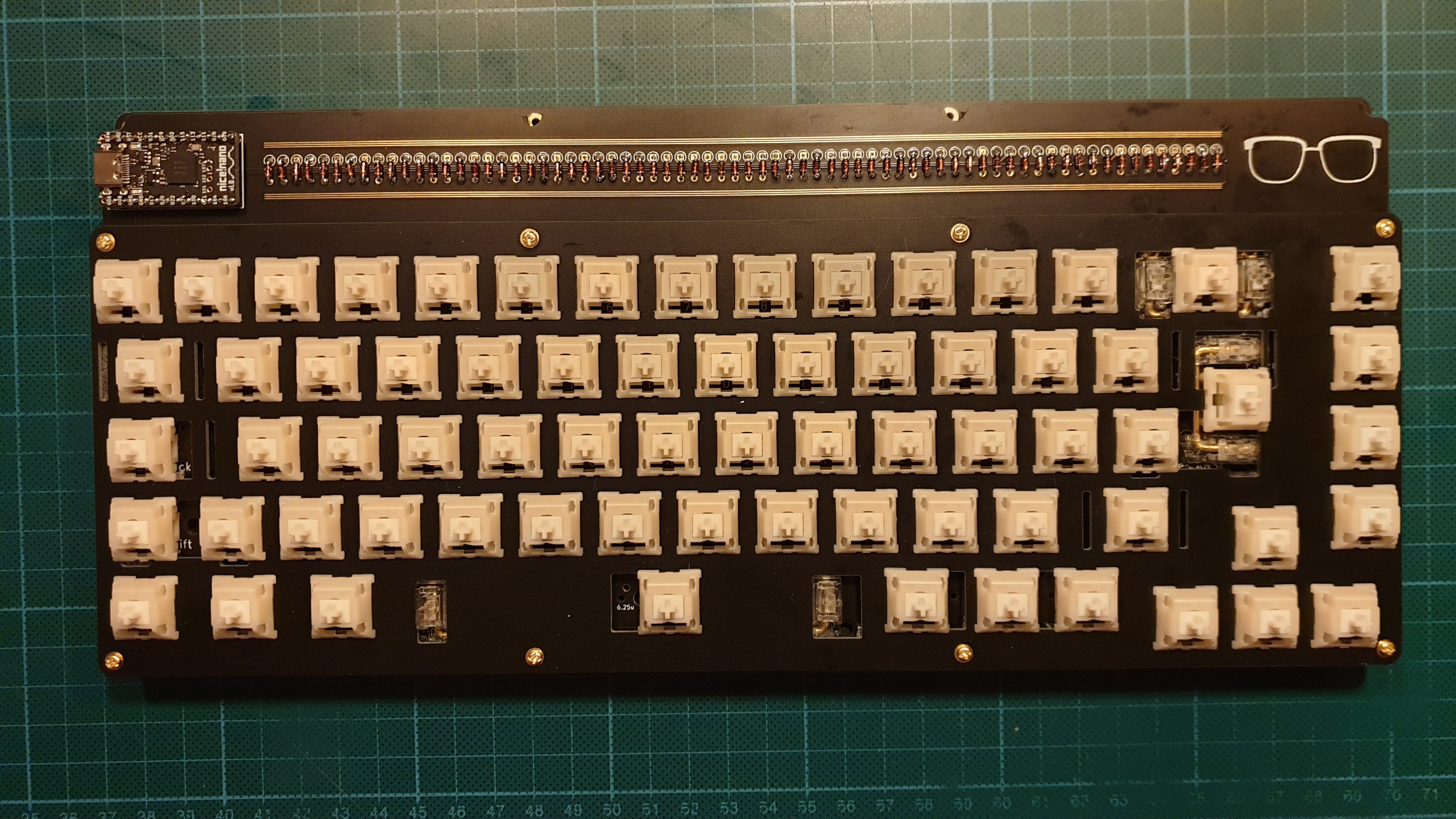
- Attach the nice!nano (which I did by socketing it so I can remove it easily if I want).
- Solder in diodes for all switches.
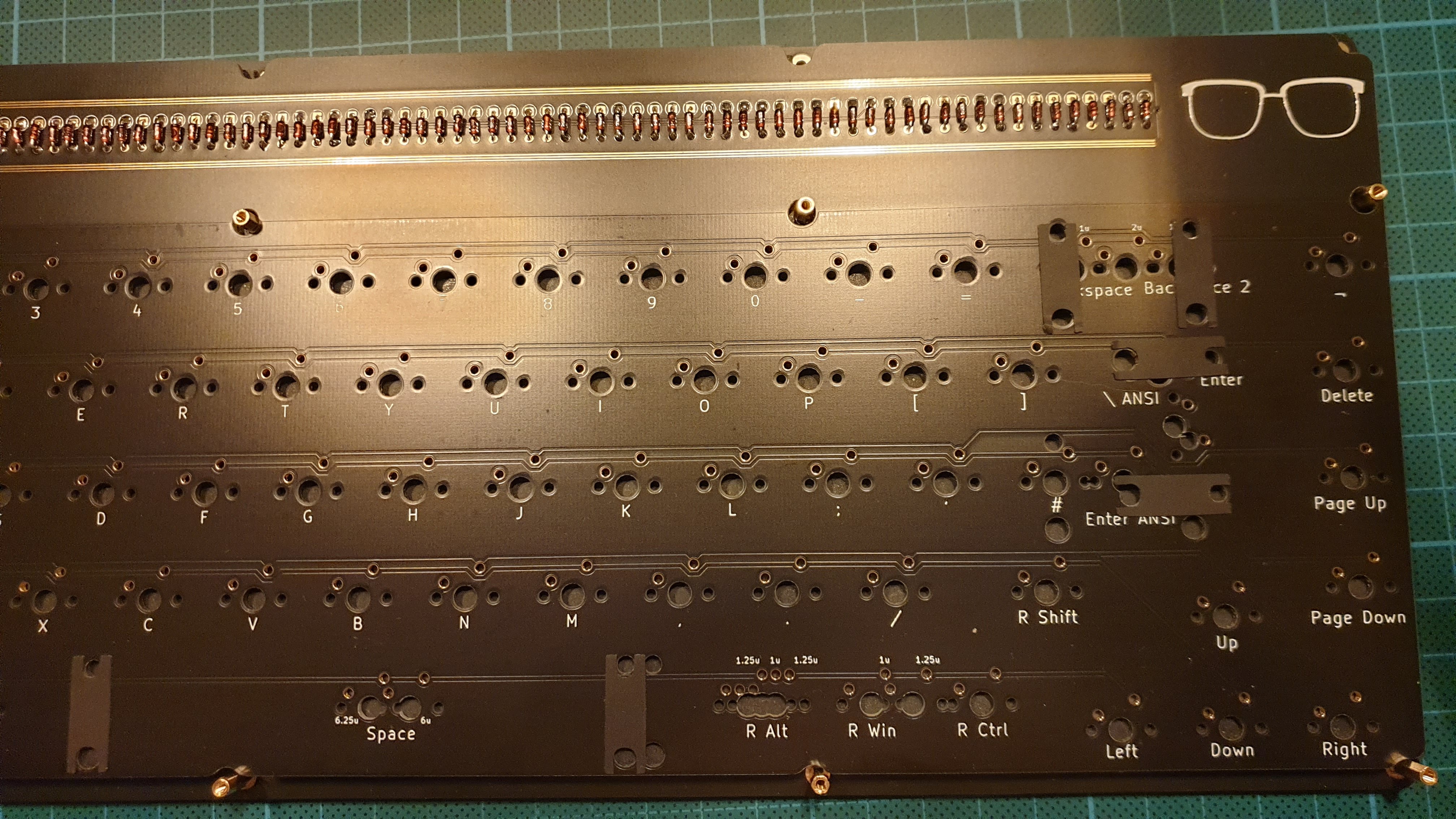
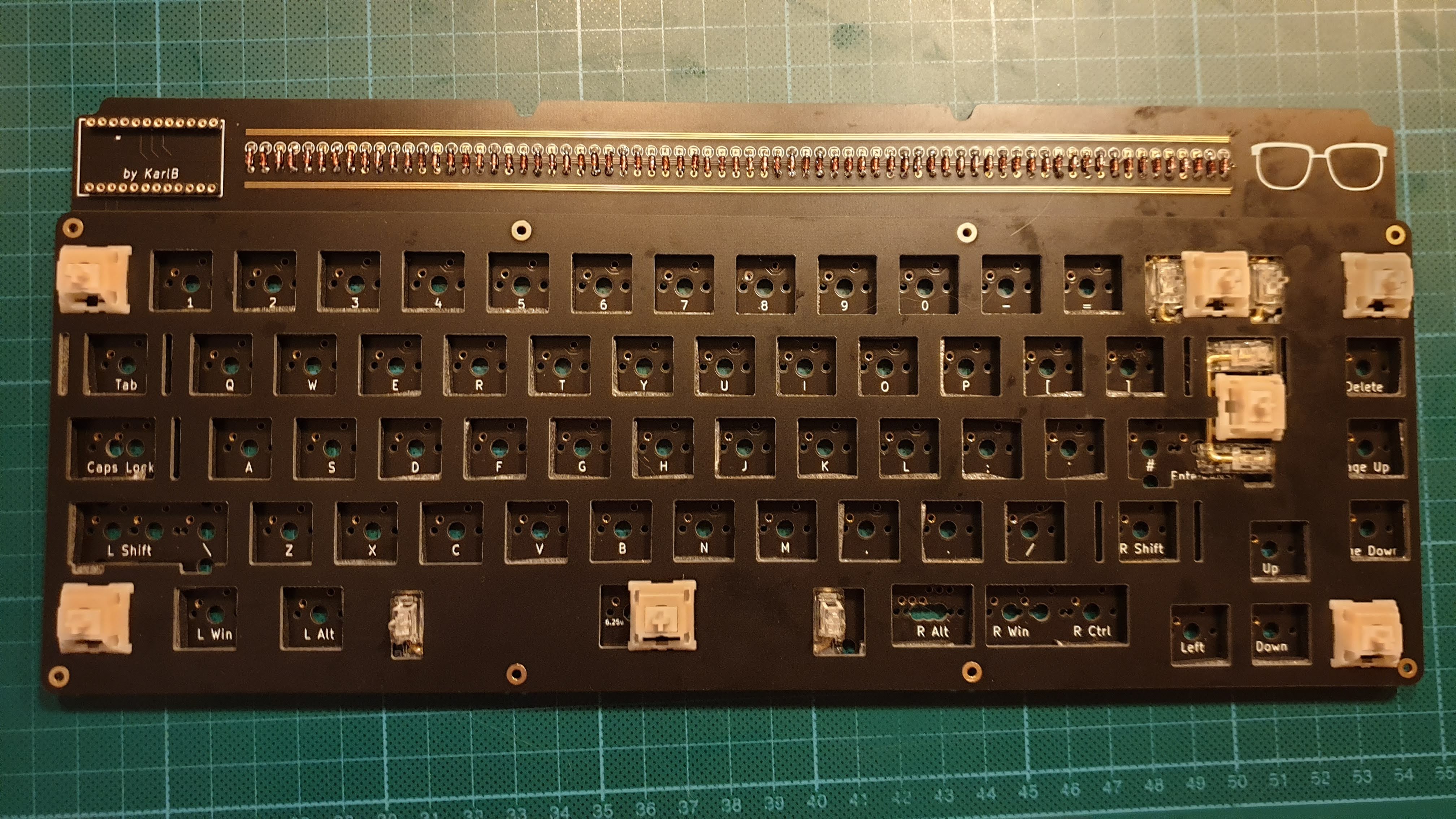
This is essentially just a bunch of soldering and ended up like this for me:
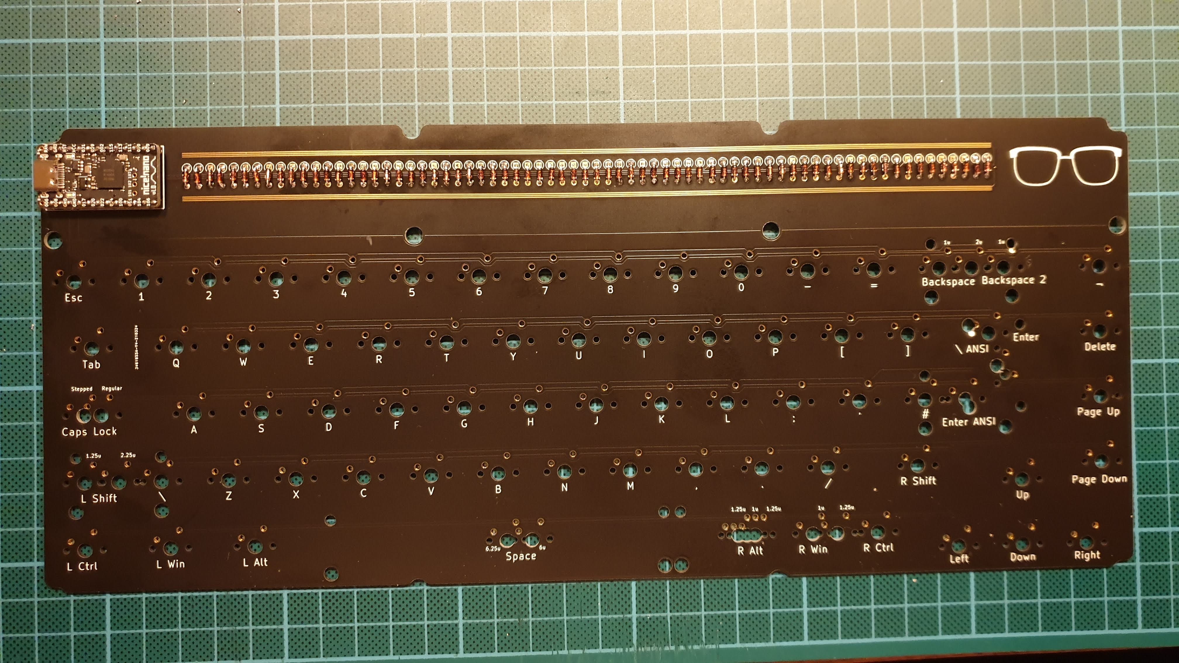
The tricky part, compared to soldering switches is that these joints are very visible and since the are on one long line, any inconsistencies show easily. I initially tried bending multiple diodes together when they where still in their package tape but I don’t think it really worked better than just bending them one by one with my hands. This was also partially due to the footprint I selected for the diode essentially requiring the diode legs to be bent as close to the diode as possible.
One thing I would be more careful about if I did it again would be to try to be consistent with the amount of solder I used and the amount of time I spent heating up the solder and components. One of the aesthetic issues with the final result is that the solder came through from the back of the board and filled part of the front for several diodes, but not all, and this is probably the inconsistency that bothers me the most.
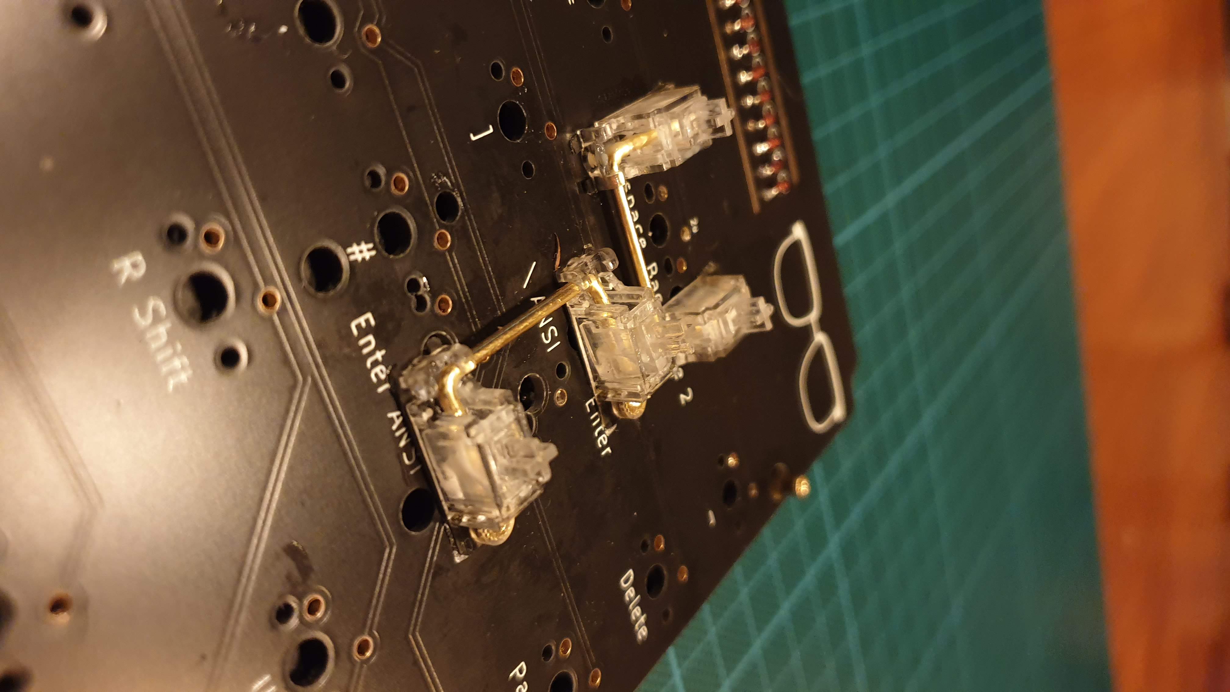
Prepare and attach stabilizers
For stabilizers I got Durock screw-in stabilizers v2 with transparent plastic and brass/golden metal details. It was the stabs I could find that I think would go best with the rest of my build (black, white and gold).
6u stabilizer
For my first build with this PCB I wanted to use a 6u space bar to allow for a 1.25u Right Alt, which is heavily used when typing with a Swedish (or any ISO) layout. I knew they aren’t that common, but luckily the ePBT 9009 kit I got for this keyboard has multiple 6u space bars to choose from. However, later when buying stabilizers I found out that 6u stabilizers are probably even more rare, especially if you want them looking a certain way. Doing a bit of research, the best course of action seemed to bend another stabilizer wire (or some other metal wire) to the correct length. Luckily, my Durock stabilizer set came with a 7u stabilizer wire that I have no plan on using so I took some pliers and a small vice and bent it to the correct size. I had to iterate once, my first bend made the wire slightly too long and it put some unwanted pressure when in stabilizer mount but lucky enough I was able to re-bend it to a good size.
Clipping
The Durock stabilizers are designed to not require clipping so did not have to do this step.
Stabilizer foam/ band-aid mod
Instead of doing the actual band-aid mod I was lazy and picked up some KBDfans stabilizer foam stickers when ordering some other stuff.
Shrink tube mod (failed/removed)
I had some shrink tube laying around that I thought I could try doing the shrink tube mod with. However, I think the shrink tube might have been too big or maybe it doesn’t work as well with the Durock v2 stabilizers, but the stabilizers ended up sticking and being sluggish so I decided to remove them instead.
Lube
Used Krytox 205g0 to lube the switches since it was the best thing I had available at home.
Attaching
After adding the stabilizers and beginning to solder in the first switches I discovered that some of the plate foam I had put it was pressing on the stabilizers, both on the screws (making )
Assemble plate-PCB package
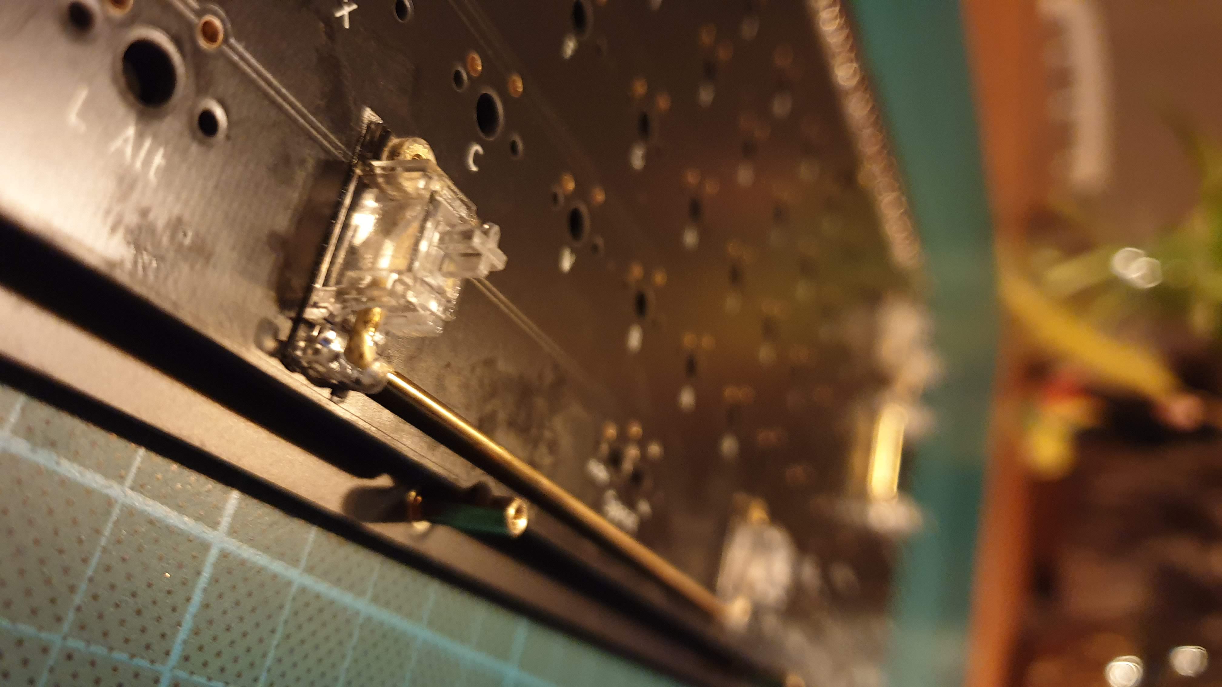
The next step was to put together the plate, prepared PCB and all the switches. My choice of switch for this build was the Gazzew Boba U4, a silent and very tactile switch, which I am very satisfied with (since I am using them to type out this build log).
This is pretty well covered in any build log or video, but a good trick is to start with attaching the corner switches. I then also soldered in the switches for keys with stabilizers since I wanted to make sure those keys felt okay before I continued (in case I had to remove all switches and modify the stabilizers, which I did do once).
Once you have the corners in place, it is fairly easy to attach and solder multiple switches at ones, I did them row by row, and you end up with a plate-PCB package with switches. Almost a full keyboard now!
Test without battery
Just to make sure I didn’t fuck anything up I went back to the computer and made sure the assembled package worked before moving on to attaching the battery.
Attaching the battery
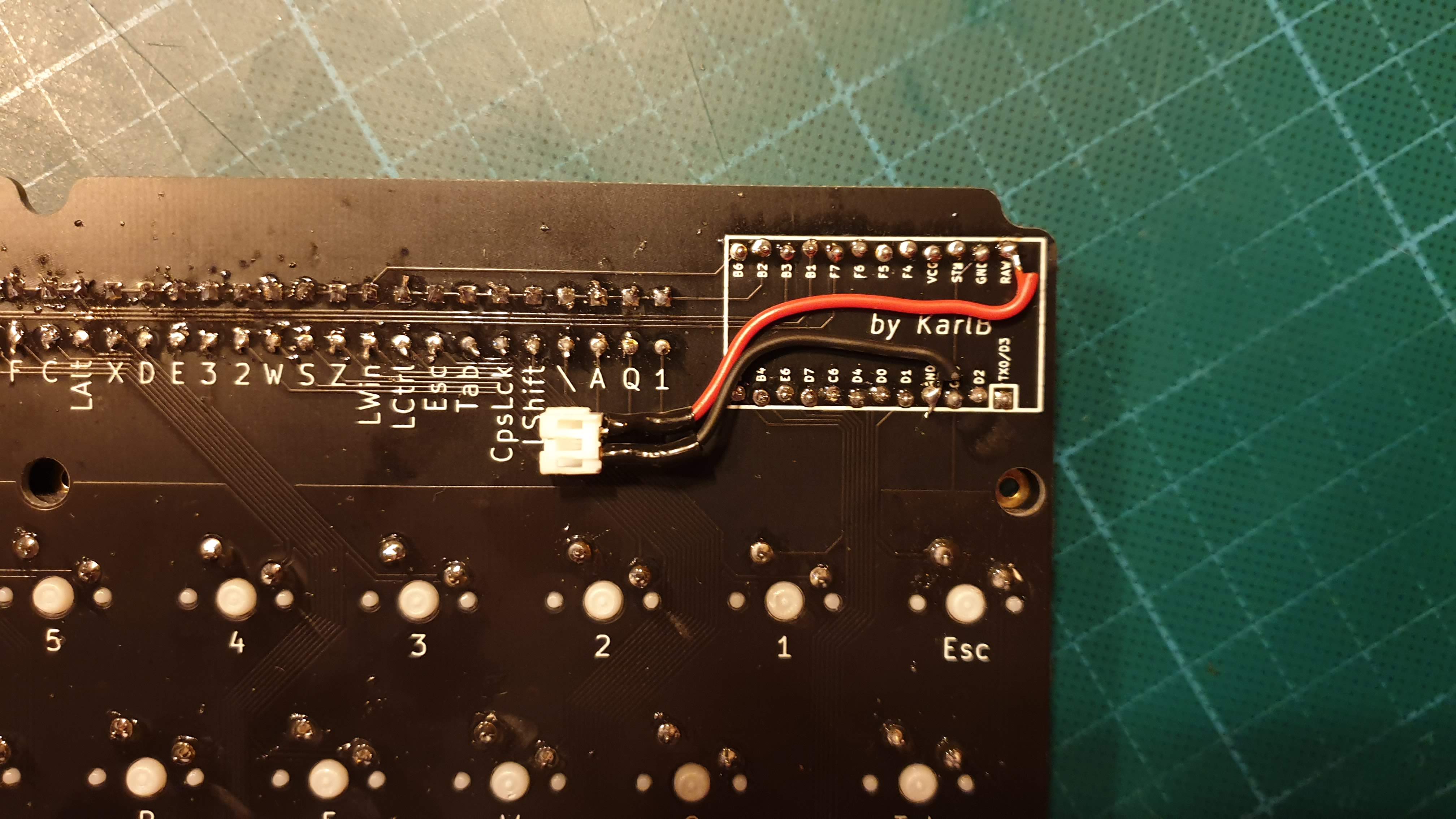
This was the part of the build I was the least sure of how I was going to do. I had bought a 130 mAh LiPo battery, since I had trouble finding the slightly smaller 301230 110 mAh battery in Sweden that is recommended when mounting it under a socketed nice!nano. I was, however, able to find a pretty good solution (in my opinion) since the space between the bottom and PCB ended up being 5 mm with my chosen spacers.
I soldered on a connector with wires to the ground and VCC pins on the back of the PCB and routed so that I could place the battery in the areas with no soldered components with legs sticking down.
I then made a cut out in the neoprene to house the battery.
Unfortunately I forgot to take a photo with the actual battery in place as well. I added a small piece of double sided tape on the side of the battery to keep it in place.
Test again, now with battery, and Bluetooth
Damn, did it feel good when I paired the keyboard with my desktop and was writing on my own designed wireless keyboard. So cool!
Assemble complete keyboard
This step is pretty simple, stack all the pieces you have together now and put on the final screws!
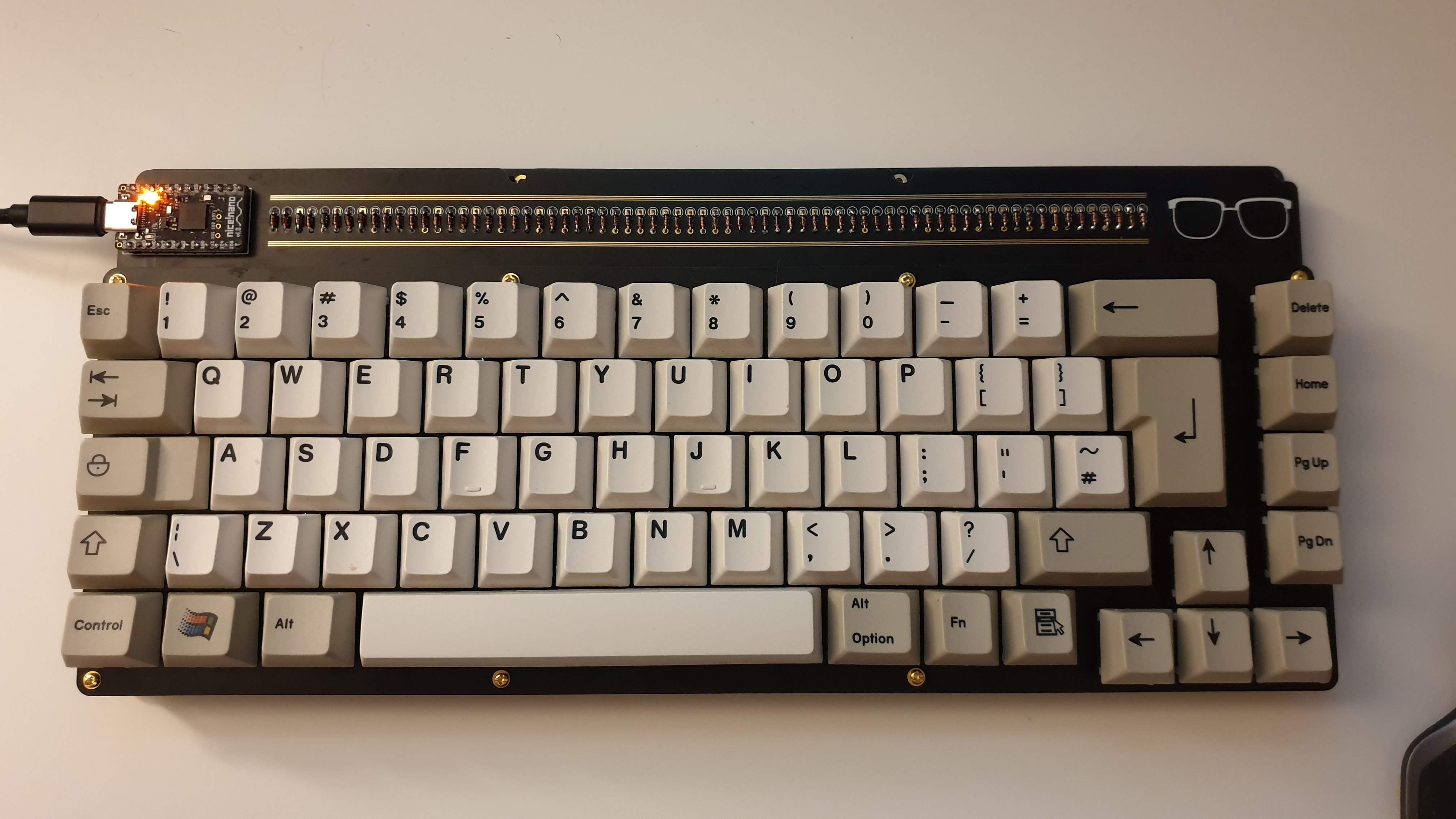
Put on key caps
So I got an ePBT 9009 kit for this, since my long term goal for this build is to also create a case and the idea is for it to have some 80s-90s computer vibes, like the 9009 color scheme. Also, I got the extra colored Win-key set, really love those and reminds me of using my grandfather’s computers (who is also the inspiration for the glass design on the board) and want that aesthetic. Not complicated to put on keycaps, but now it is more easy to see my chosen layout.
Final testing
Make sure everything works and feels like you expect it to, which it did! I had a worry that the right arrow key might hit the bottom right case screw when pressed down fully but luckily it just about fits without any modification, win! And now you can just enjoy your keyboard!
Oh, wait…
Design and order an acrylic window for the top
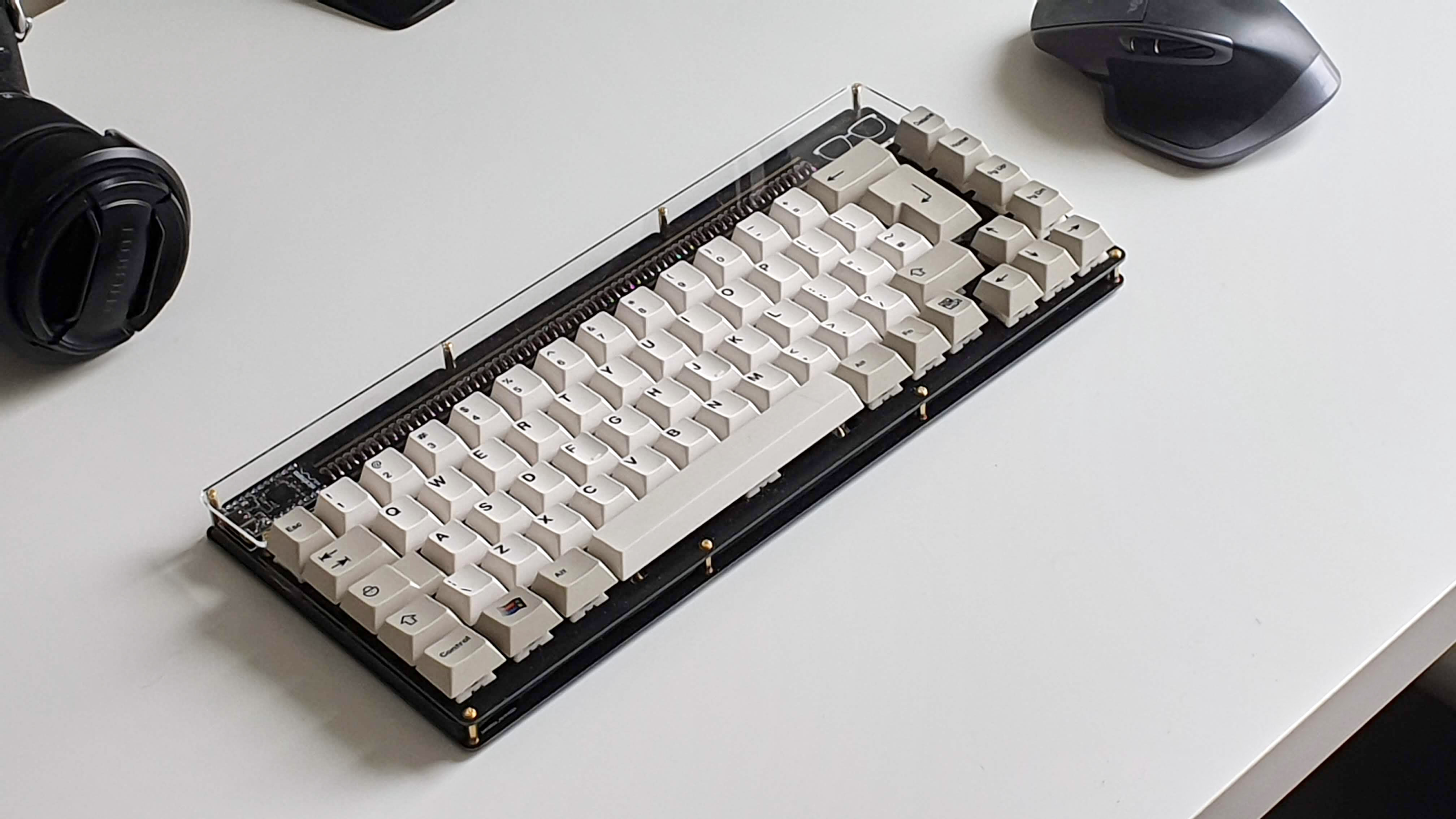
I wasn’t sure how if I should use an acrylic window covering all eight screws on top or if the overlap would look weird so I created two versions. One covering all eight screws on the top part, and one version that only uses the four screw holes on the top of the bottom, which is a bit weaker structurally. I ordered both versions and in both 2 mm and 3 mm clear acrylic to test at home.
Turns out 2 mm acrylic is plenty strong with this amount of screws and without a case the eight screw mount version definitely looks better in my opinion. I do plan on designing a case for it and might use the four screw mount window pieces I now have left over as the window in that case. instead.
And with the acrylic window on, version 1 of the KBIC65, aka Observer65, is finally complete!
Notes if I ever make a V2 or if someone attempts a GB
PCB front glasses should be in copper
I accidentally forgot to remove a silk screen version of the glasses on the front of the PCB, resulting in what should have been bare gold-ENIG finish copper glasses being white silk screen instead (with a tiny, almost indistinguishable copper margin around them).
Add holes for soldering on a battery connector
I did not plan enough for attaching the battery and the design would have been neater if there were ports for soldering a battery connector directly.
Maybe make space bar cutouts in plate and/or PCB to house battery
I originally had a plan to put the battery between the PCB and the plate. Unfortunately the battery I got was too thick (there are thinner ones though) but it could possibly have fit if I had more cutouts around the space bar and put the battery there. The current solutions is not that bad though and will allow me to put in a larger battery as long as it is at most 5 mm thick.
Move the JLCPCB manufacturing number on the bottom plate
If you choose to have the sun image facing out on the bottom, the production number from JLCPCB will show upward on the edge of the bottom plate, would probably be better to put it on the side or top somewhere instead.
Update August 2021
I ordered new spacers and found that M2x15mm female-female and M2x3mm+4mm thread male-female spacers are a much better combo for the top window (reduces height different to 0.4mm, which is OK). In addition, Nicell released the nice!nano v2.0 and ZMK released a Zephyr update. Biggest difference is probably the nice!nano v2.0 but the combination has probably pushed my battery life using a 130 mAh LiPo battery to 2 months! Also, having used the keyboard for a while now, I just love the feel. I think the combination Boba U4 switches and the neoprene and foam filled FR4 stack just hits the spot for me.
After a request on GitHub I have also created a QMK fork for the KBIC65 that I have confirmed works using an Elite-C rev 4.